
#103247
Tue Jun 19 2007 09:19 PM
|
Joined: Jun 2004
Posts: 2,131 Likes: 76
Veteran Member
|
OP

Veteran Member
Joined: Jun 2004
Posts: 2,131 Likes: 76 |
This month's pump of the month will be the Bowser 310, 318, 410, and 418.
The Bowser 310 clock face Xacto Sentry pump was produced between 1929-1934. The Bowser 318 Varley Sentry is basically the same pump as the 310 but with a Varley meter, and was produced from 1930-1934.
The Bowser 410 Xacto Sentry pump was produced between 1933-1937. The Bowser 418 Varley Sentry was again the same pump as the 410 but with a Varley meter, and was produced between 1933-1936.
|
|
|
Please - NO offers to Buy or Sell in this forum category
Statements such as, "I'm thinking about selling this." are considered an offer to sell.
|
|
#103248
Tue Jun 19 2007 09:22 PM
|
Joined: Jun 2004
Posts: 2,131 Likes: 76
Veteran Member
|
|
OP
Veteran Member
Joined: Jun 2004
Posts: 2,131 Likes: 76 |
I will breakdown the 410 Xacto Sentry pump. The base is in three tiers; outside dimensions are 17" X 19 1/2". There are three legs 68 1/4" long. After the legs are attached to the base the motor base is connected to the legs. 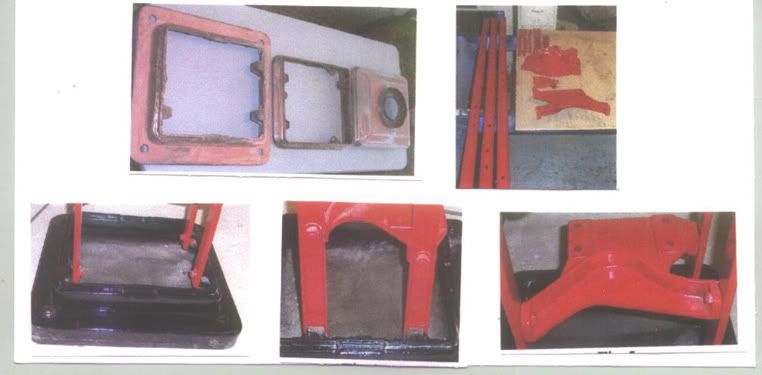 The middle collar is next to be installed on the legs, dimensions are 14 1/4" X 13 1/4". The distance between the base and collar for the lower skins to fit is 46 5/8". Make sure everything is square. The underwriters tag and the Bowser Xacto tag can now be put on. 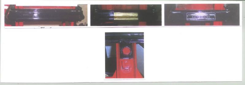 The light reflectors are installed on the top. The top can now be installed on the legs, dimensions are 14 3/8" X 13 3/8". There is a 7" globe ring that is spot-welded on the top. The distance between the collar and top for the upper skin to fit is 18 1/4", again make sure everything is square.  [This message has been edited by gatorgaspumps (edited 06-19-2007).]
|
|
|
#103249
Tue Jun 19 2007 09:34 PM
|
Joined: Jun 2004
Posts: 2,131 Likes: 76
Veteran Member
|
|
OP
Veteran Member
Joined: Jun 2004
Posts: 2,131 Likes: 76 |
The light assy. can now be attached to the legs. It goes on the side with the single leg. 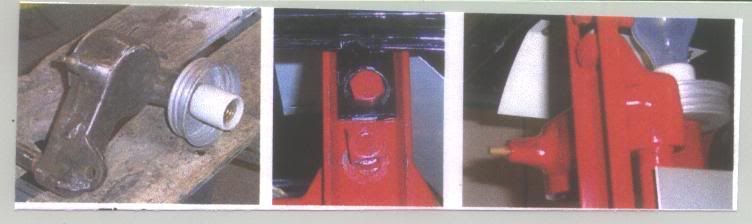 The meter base and Vis gauge pipe can now be installed. The pipe must be installed on the meter base before it is installed on the middle collar. The pipe comes out the side with the two legs. This is the correct Vis gauge for this pump. 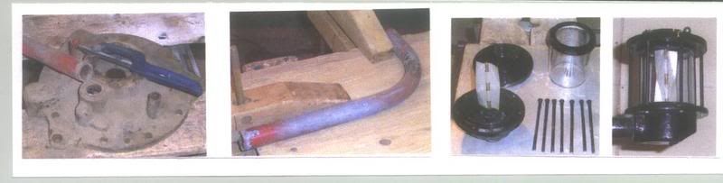 The clock assy. can now be installed. From the base of the reset knob to the outside edge of the reset support bracket is 3/4". This allows room for the skins to slide by when mounting. The reset is on the side with the single leg. 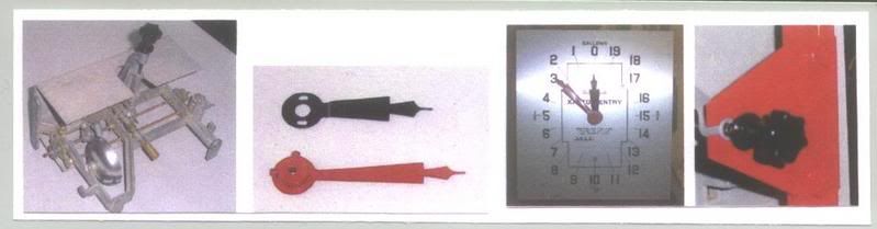 [This message has been edited by gatorgaspumps (edited 06-19-2007).]
|
|
|
#103250
Tue Jun 19 2007 09:43 PM
|
Joined: Jun 2004
Posts: 2,131 Likes: 76
Veteran Member
|
|
OP
Veteran Member
Joined: Jun 2004
Posts: 2,131 Likes: 76 |
The nozzle receiver and hanger can now be installed on the side with the two legs. 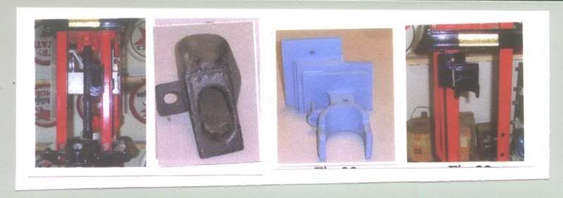 The frame is now ready for the skins to be attached. The bottom skins are 46 1/2" long. The top skins are 18" long. 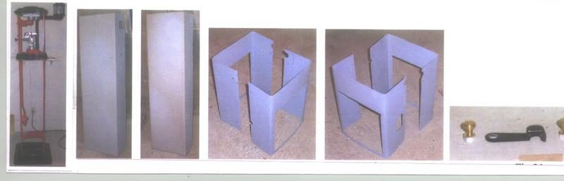 The window frame dimensions are 15 1/2" X 11 3/4". The stainless collar is 1 1/8" deep. The glass is 12" X 11". 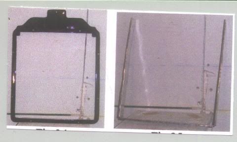 [This message has been edited by gatorgaspumps (edited 06-19-2007).]
|
|
|
#103251
Tue Jun 19 2007 09:51 PM
|
Joined: Jun 2004
Posts: 2,131 Likes: 76
Veteran Member
|
|
OP
Veteran Member
Joined: Jun 2004
Posts: 2,131 Likes: 76 |
This is the finished pump. It was painted with Acrylic Urethane black and PPG DCC 45132 green. 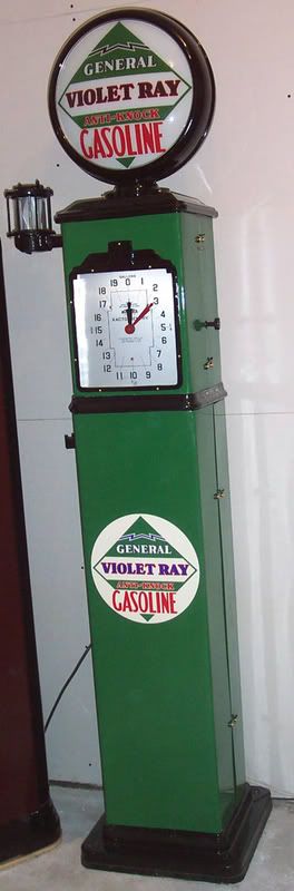 Here is a picture of a 310 Xacto Sentry taken at a swap meet years ago.  Here is a picture of two 318 Varley Sentry pumps. 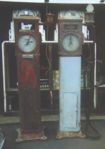 [This message has been edited by gatorgaspumps (edited 06-19-2007).]
|
|
|
#103252
Tue Jun 19 2007 10:01 PM
|
Joined: Jun 2004
Posts: 2,131 Likes: 76
Veteran Member
|
|
OP
Veteran Member
Joined: Jun 2004
Posts: 2,131 Likes: 76 |
This is a close up of a 318, notice the hose outlet on the Vis gauge drops straight down. I'm not sure if it was changed years ago or if it is original. Notice the light switch button is on the right side just above the add glass. 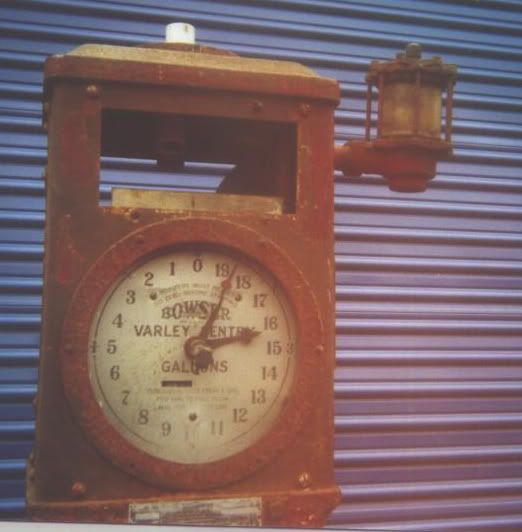 This is a close up of the other 318, notice the hose outlet on the Vis gauge goes out at a 45. This is what I have seen on the majority of the Bowser pumps. Notice also the light switch button hole is on the right side just below the add glass. 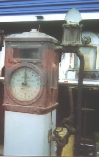 This is the correct flexible nozzle for a 318. 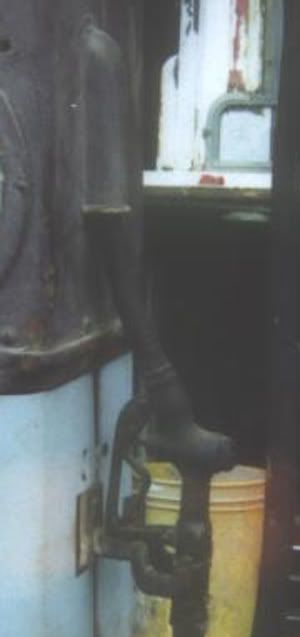 Well this is all I have; let's see some pictures and comments of differences in these pumps. If you need a picture posted send it to me, I'll be glad to post it for you. Richard [This message has been edited by gatorgaspumps (edited 06-20-2007).]
|
|
|
#103253
Wed Jun 20 2007 02:09 PM
|
Joined: Dec 2006
Posts: 3,369 Likes: 7
Veteran Member
|
|
Veteran Member
Joined: Dec 2006
Posts: 3,369 Likes: 7 |
I am assuming the Varley Meter pump resets from the face???????
Can you post a picture of what the clock unit sets on? For the 410? Is it the same in the Varly Sentry????
Veeder Root Rebuilds.....since 1987
Veeder Root Identification CD
Gas Pump Clock Repair
jkyocom@bellsouth.net
|
|
|
#103254
Wed Jun 20 2007 03:11 PM
|
Joined: Oct 2000
Posts: 22,780 Likes: 5
Veteran Member
|
|
Veteran Member
Joined: Oct 2000
Posts: 22,780 Likes: 5 |
Both the 310/318 & 410/418 clock mech's bolt to the measuring unit, not the frame.
The 310/318 reset is on the face. The 410/418 reset is on the side.
This is a Patent drawing for the 310 http://www.google.com/patents?vid=USPAT1986162&id=OJF5AAAAEBAJ&pg=PR2&dq=DISPENSING+NOZZLE+FOR+GASOLINE&num=100#PPA2,M1
and a 410. Notice the special NOZZLE. Does anyone have one ? http://www.google.com/patents?vid=USPAT2065052&id=aFJPAAAAEBAJ&pg=PP1&dq=gasoline+dispenser++sample&num=100&as_drrb_is=b&as_minm_is=1&as_miny_is=1904&as_maxm_is=1&as_maxy_is=1940#P PP2,M1
This is for a 410 w/ CACULATING DIAL http://www.google.com/patents?vid=USPAT2169635&id=mjtXAAAAEBAJ&dq=gasoline+LIQUID+DISPENSING+sample&num=100&jtp=1#PPA6,M1
I've never heard of one till I found this.
db
[This message has been edited by Dick Bennett (edited 06-20-2007).]
|
|
|
#103255
Wed Jun 20 2007 05:00 PM
|
Joined: Oct 2000
Posts: 22,780 Likes: 5
Veteran Member
|
|
Veteran Member
Joined: Oct 2000
Posts: 22,780 Likes: 5 |
On the XACTO SENTRY the top of measuring mech. is part of the Center casting, so there is a place to mount Clock mech. On the VARLEY SENTRY the measuring mech. is bolted to the center casting, so when/if it's removed you will have to fabricate something to hold the Clock mech. This my CANADIAN VARLEY SENTRY w/ a Morrision nozzle.  db [This message has been edited by Dick Bennett (edited 06-20-2007).]
|
|
|
#103256
Wed Jun 20 2007 07:46 PM
|
Joined: Jun 2004
Posts: 2,131 Likes: 76
Veteran Member
|
|
OP
Veteran Member
Joined: Jun 2004
Posts: 2,131 Likes: 76 |
On the fifth series of pictures left side shows the meter base which attaches to the middle collar. If you look at about the 4 o'clock and 11 o'clock position you see two raised areas, this is where the clock meck. attaches by two 1/4" bolts. Here is a picture but I had to blow it up so it is fuzzy. Richard 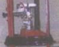
|
|
|
#103257
Thu Jun 21 2007 09:09 PM
|
Joined: Dec 2006
Posts: 3,369 Likes: 7
Veteran Member
|
|
Veteran Member
Joined: Dec 2006
Posts: 3,369 Likes: 7 |
The way the nozzle is designed , it looks like it would be a two speed. Two triggers two valves and two different size orifice.
Veeder Root Rebuilds.....since 1987
Veeder Root Identification CD
Gas Pump Clock Repair
jkyocom@bellsouth.net
|
|
|
|
|


